Mounting of motors/machinery
Last issue’s article dealt in particular with the relevance of structure-borne sound in synchronous and asynchronous drives of lifts without machine rooms. What might potential solutions look like here?
By Ulrich Nees and Jan König
The goal of elastic drive-/machine mounting is to keep the transmission of structure-borne noise through all the attachment elements, including the foundation (drive frame), as low as possible. In smaller machines, this can be achieved with an elastic set-up. Larger machines and ones subject to many load changes (accelerations and decelerations) should have a rigid set-up (1).
Explanation: a foundation (rigid set-up) is described as solid if the vibration speeds measured in horizontal and vertical directions at the machine feet or the frame do not exceed 30 percent of the maximum vibration speeds (measured on the drive/machine) (1).
At low speeds (≤ 600 min-1) with many load changes, i.e. accelerations and decelerations of the car, a rigid set-up (2) of the drive is advisable. In the case of high speeds (≥ 600 min-1) and very few load changes EL3 mounting directly beneath the drive is no problem (2).
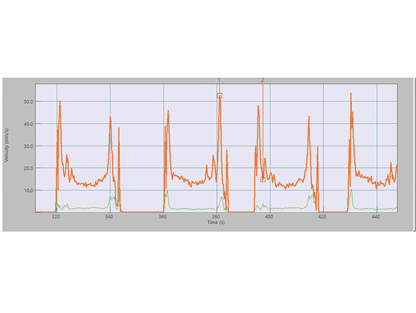
 Diagram 1: EL3 mount v = 50 mm/s Photo: © Aufzug-Systeme + Beratung Ulrich Nees
The further away the vibration isolation is attached from the (disruption) source (e.g. drives, speed governor), the lower the structure-borne sound emissions into the lift shaft wall are.
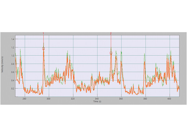
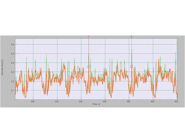
Three measurements of vibration speeds (2) on comparable drives can be seen here. Different versions were selected here: first an EL3 mount, then an EL1 mount and as third diagram, a rigid set-up.
Diagram 1: EL3 mount v = 50 mm/s
 Diagram 2: EL1 mount v = 1.3 mm/s Photo: © Aufzug-Systeme + Beratung Ulrich Nees
Diagram 2: EL1 mount v = 1.3 mm/s
Diagram 3: Rigid set-up v = 0.6 mm/s
The measurements of the EL3 mounts up to 50 mm/s occur during the acceleration and deceleration of the drive. The “tipping” of the drive through acceleration and deceleration of the lift is the cause of the high vibration speeds (Diagram 1), which are then transmitted as structure-borne sound emissions into the lift shaft wall.
 Diagram 3: Rigid set-up v = 0.6 mm/s Photo: © Aufzug-Systeme + Beratung Ulrich Nees
As a result, the permissible structure-borne sound level on the lift shaft wall does not comply with DIN 8989 / Table 3. Tipping of the machine affects the housing of the machine, the shaft mount and the shaft itself.
DIN EN1299:1997+A1:2008 describes special requirements, such as those for mechanical stability. The greater the distance between the centre of gravity of the machine and mount, the more caution is required and the greater the wear. This also applies if lateral compressive forces (DIN EN 60034-14) are not captured.
The following requirements have to be met if vibration isolation is used:
DIN EN 1299: 2009-02 Mechanical vibration and shock – Vibration isolation of machines – Information for the application of source isolation; German version DIN EN1299:1997+A1:2008
VDI 2064: 2010-11 Active vibration isolation
VDI 2062 Sheet 1: 2011-05 Vibration isolation – terms and methods
VDI 2062 Sheet 2: 2007-11 Vibration isolation – vibration isolation elements
DIN EN 13501-1: 2019-05 Fire classification of construction elements and building elements – Part 1: Classification using data from reaction to fire tests
This article considered the areas of use of elastic mounting systems as well as their limits. Of course, not just the mounting of drives, but also their assembly is important. This will be the subject of the next article.
Jan König is the proprietor of the engineering firm (VID) Ing4Lifts.
Ulrich Nees is the proprietor of “Aufzug-Systeme + Beratung Ulrich Nees”.
(1) DIN EN 60034-14
(2) see Diagrams 1 to 3
More information: ing4lifts.de
aufzugsystemeberatung.de


Write a comment