Better adjustment of rope and drum
In a current doctoral thesis at the Institute of Mechanical Engineering of TU Clausthal, a new approach has been developed on how to analyze the behaviour of ropes on multi-layer spooled rope drums and better adjusting the system components with each other.
The goal of the study was optimal adjustment of rope and drum as system in order to guarantee safe use. Among other things, the parameters for optimisation of the system are the diameter and deformation behaviour of the rope and groove and flanged wheel geometry of the drum.
The occasion for the examination: use of fibre ropes is increasingly common, yet there are not as many research results for them as for wire ropes. But when it comes to wire ropes, particular applications also require optimisation – for example, in the case of reduced rope force in the lower layers of the winding pack.
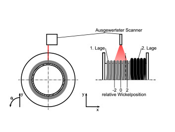
Examination of the winding behaviour of the rope on the drum was performed with laser profile scanners. For this purpose, they were mounted above the drum in one plane with its axis of rotation (Figs. 1 and 2). [1] and [2]
Pictures of the drum surface
 Fig. 2: Diagram of the scanner arrangement. Photo: © Martin Schulze
During the spooling of the rope, pictures of the drum surface were first made. The layers were then recorded one after another during the spooling. The evaluation assigned each winding in the visual range of the scanner a characteristic point. The x-coordinates were normalized on the groove width in the presentation. As a result, distance 1 ideally exists between two windings (Fig. 2).
The characteristic course of the rope in the multi-layer spooling arises from the necessary to and fro winding between the flanged wheels. When the uneven layers follow a left-turning helix, the even ones follow a right-turning helix.
Greater winding height in the cross-section area
As a result, the winding height of the rope can no longer be consistent on the second layer. In the parallel area, the rope lies in the valley of the lower layer. In order to reach the next valley after every half drum turn, it has to run over the underlying winding. This produces the greater winding height in the cross-section area.
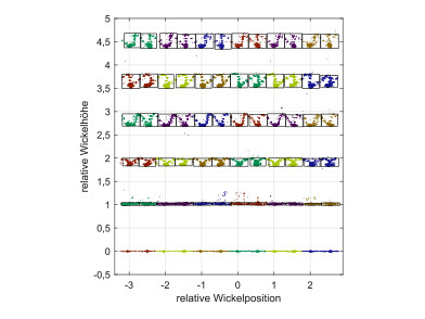
 Fig. 3: Section of an idealised winding pack of a wire rope. Photo: © Martin Schulze
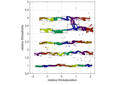
The course of the winding is presented in Fig. 3 and 4. The drum can be seen on the coordinate 0. Layers one to five can then be seen. Points that belong to a half-turn are grouped together with a black square.
Fig. 3 shows an almost ideal typical course of a wire rope on a suitable drum with the correct application parameters, such as rope force, deflection angle, etc. This ideal typical behaviour can be recognised by the parallel areas lying on top of each other and by the increasing height difference as the number of layers increase between the parallel and intersecting areas in one layer.
Use as live monitoring
Analysis of the course of winding is the basis for optimising the interplay of rope and drum. Comparison of the winding packs of wire and fibre rope (Fig. 3 and 4) indicates the better winding quality for the wire rope on the basis of the greater symmetry of the wire rope winding pack.
Further information is provided by comparing the experimentally determined position of the rope with a theoretically determined rope position. This also permits quantifying the winding quality.
Apart from the gradual optimisation of the system, later use as live monitoring is also conceivable. As a result, imprecise winding can be detected directly upon occurrence and a critical operating condition prevented.
Optimised adjustment of rope and drum
 Fig. 4: Section of a winding pack of a fibre rope with an intrusion of the fifth into the fourth layer. Photo: © Martin Schulze
Fig. 4 is an exemplary presentation of the course of winding of a fibre rope. Since the rope does not optimally match the drum, a winding error occurs: in the fifth layer the rope cuts into the fourth layer (relative winding position approx. 0.8).
If this jamming is not resolved during winding, the jerky rewinding would produce a critical operating condition with possibly catastrophic effects.
Thus, by using the procedure described here, optimised adjustment of rope and drum as well as monitoring in use can enhance safety in the rope-drum system.
Dr.-Ing. Martin Schulze, Prof. Dr.-Ing. Armin Lohrengel (Institut für Maschinenwesen der TU Clausthal), Prof. Dr.-Ing. Wolfram Vogel (GUT ACHTEN – Sachverständigenbüro für Aufzugtechnik)
More information: Here you will find the link to the detailed description of the construction.
-----------------------------------------------------------------------------------------------------------------------------------------------------------
[1] Schulze, Martin (2016): ‘Einsatz von Laser Profil Scannern bei der Mehrlagenwicklung von Seilen‘. [‘Use of laser profile scanners in multi-layer winding of ropes.’] In: Mitteilungen aus dem Institut für Maschinenwesen der Technischen Universität Clausthal 41, p. 113–126.
[2] Schulze, Martin (2019): Kompatibilität von Faserseil und mehrlagig bewickelter Seiltrommel, Technische Universität Clausthal, Dissertation


![Fig. 1: Laser profile scanner above rope drum to investigate the multi-layer winding pack. [2]](https://images.v-h.media/WCQKq0QObi9XSzaAlRBimKLZqi4=/73x49/https%3A%2F%2Fv-h.media%2Fvah%2F%3Ftitle%3D24649%26size%3D%26sch%3D2b60b268c2075c02120d749452e8134a3b5d6aeee7f26ffcc12cf2c5f4567a4e%26post_id%3D0%26end%3D0)


Write a comment